(Arduino Beginner) Tutorial 4: Push-button
6 minutes to readGood day! Welcome back to another Arduino tutorial for beginner. For today project, I am going to show you the basic usage of a push button. Let’s begin, shall we?
For this tutorial, you are required the following materials
- Arduino UNO - 1 unit
- Resistor (around 150 ohm) - 1 unit
- Breadboard - 1 unit
- Push-button - 1 unit
Task 1: Understanding the concept
Before we jump into the hands-on, you need to understand how to operate a push-button as an input. Basically, there are two types of button configuration which is
1) Active High
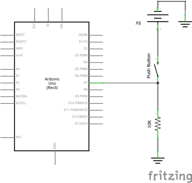
The figure above shows the push button in the active high configuration.
When the push button is **NOT PRESSED** (open circuit)
The input pin 7 on the Arduino detects logic 0 (LOW). This is because there is no current flow into it.
When the push button is **PRESSED** (closed circuit)
The input pin 7 on the Arduino detects logic 1 (HIGH). This is because there is a current flow into it. This can be explained by the path chosen by the current. The current is a smart element. When the button is pressed, the current has two way to choose for. Path to the Arduino or path to the resistor. The easy way or the hard way? Of course the current will choose the easy way a.k.a the Arduino path. This is due to the internal resistance of the Arduino is minor when compared to the 10k ohm resistor.
2) Active low
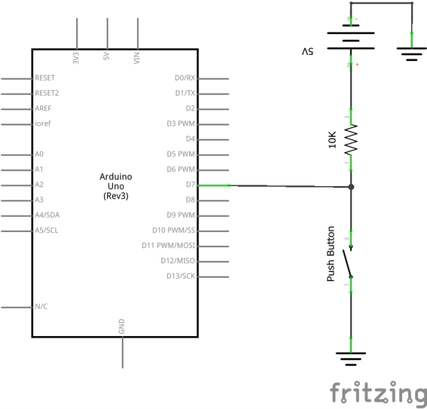
The figure above shows the push button in the active low configuration. The only difference with the active high configuration is the position of the push-button and the resistor.
When the push button is **NOT PRESSED** (open circuit)
The input pin 7 on the Arduino detects logic 1 (HIGH). This is because the current only have one path to choose for which is the Arduino path.
When the push button is **PRESSED** (closed circuit)
The input pin 7 on the Arduino detects logic 0 (LOW). Similar to the active HIGH configuration, the current has two way to choose for. This time is a little bit different, the current can either flow through the wire with no resistor or the Arduino with a minor internal resistor. The current will choose the wire path due to the negligible resistance of the wire. Amazing huh.
3) Summary
The table below summarizes the push-button configuration with respect to Arduino input value.
| Setup | Arduino input (Button not pressed) | Arduino input (Button pressed) |
|---|---|---|
| Active High | Logic 0 (LOW) | Logic 1 (HIGH) |
| Active low | Logic 1 (HIGH) | Logic 0 (LOW) |
Task 2: Hands-on
1) Basic hands-on
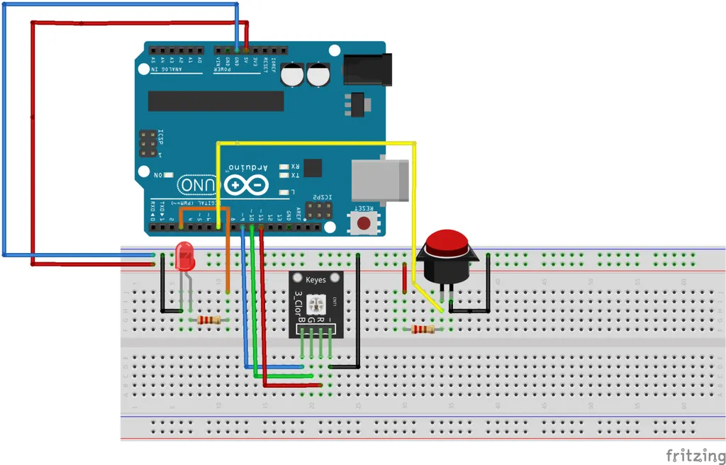
Time to get your hand dirty. Before we start to upload the code, you might ask me the pin connection in the figure above look complicated. Rest assured, as I said at the end of project 0 where every project posted in this series are connected. If you are not interested in following-up this series, you just need to connect the button and resistor. On the other hand, if you are interested, you can follow my project 1 (blinking LED), project 2 (serial communication) and project 3 (PWM) tutorial write-up.
For this hands-on, I’m going to use active low configuration. Let’s compile and upload the following code.
#define LED 3
#define button 7

void setup()
{
  pinMode(LED,OUTPUT);
  pinMode(button,INPUT);   // Set button as Input
}

void loop()
{
  boolean ButtonState = digitalRead(button); // read button

  if (ButtonState == 0) digitalWrite(LED,HIGH);
  else if (ButtonState == 1) digitalWrite(LED,LOW);

}
Let me explain the following line
(Line 12) digitalRead(Pin) - Read the Arduino digital input.
2) Hands-on tips
If you do not have any resistor to build the push-button input, the Arduino internal PULL_UP mode might be the answer for you. Please be noted that Arduino internal pull-up is an active-low configuration. Use a resistor if you are looking for active-high configuration. The configuration of internal pull-up:
...

void setup()
{
  pinMode(button,INPUT_PULLUP);   // Set button as Input with internal pull-up
}

...
3) Latching the input
I leave this task as an assignment to let you figure out what is going on. If you have a question, DM me through email or twitter.
#define LED 3
#define button 7

boolean OldButtonState; //define last button state

void setup()
{
  pinMode(LED,OUTPUT);
  pinMode(button,INPUT);   // Set button as Input
}

void loop()
{
  boolean ButtonState = digitalRead(button);

  if(ButtonState != OldButtonState)  //detect change in button state
  {
    if(ButtonState == 0)
    {
      digitalWrite(LED,!digitalRead(LED)); //toggle LED
    }
    delay(50);
  }
 OldButtonState = ButtonState;   //register the old button state
}
Task 3: What have you learned from this tutorial
- You have learned the basic concept on configuring a push-button input
- Basically you have learned the following code from this tutorial
- digitalRead(A) - Read a digital value
- pinMode(A,INPUT_PULLUP) - Set the input with internal pull-up resistor
Conclusion
That’s all for the basic push-button tutorial. Hope you learn something new today. See ya ;)
tags: arduino - beginner - tutorialThanks for reading. Follow my twitter for latest update
If you like this post, consider a small donation. Much appreciated. :)