(Arduino Beginner) Tutorial 3: Pulse Width Modulation (PWM)
6 minutes to readGreeting there, welcome back to another Arduino tutorial for beginner. Today we are going to talk about Pulse width modulation which is also known as PWM in short. Without further ado, let’s begin.
For this tutorial, you are required the following materials
- Arduino UNO - 1 unit
- Resistor (around 150 ohm) - 1 unit
- Breadboard - 1 unit
- LED (Red color) - 1 unit
- Tri-color LED module - 1 unit
Task 1: Understanding the concept
Task 1-1: What is PWM
Pulse width modulation is a technique for getting analog results with digital mean. The concept is On and OFF the digital signal in the fastest way which is about 500 Hz or 2 ms. Rumour has it that the fastest speed human can catch is around 60Hz or 33ms. We use a parameter called duty cycle to obtain our desired analog value. For example, 100% duty cycle gives 5 VDC, 50% for 2.5 VDC and finally 0% for 0 VDC with respect to Arduino PWM output.
Task 1-2: How to identify PWM on an Arduino
Let’s take Arduino UNO as an example.
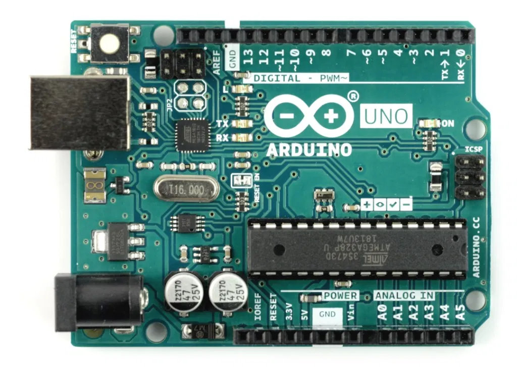
All the PWM came with a ~ label on the board. By referring to the figure above, the PWM located at Pin 3, 5, 6, 9, 10 and 11. There are a total 6 PWM pins available on Arduino UNO. The number of PWM pin all depends on the board model. For example, Arduino Mega has 15 PWM pins instead of 6. That’s all for the basic concept of PWM. Let’s proceed to our first hands-on.
Task 2: Hands-on
This section covers 2 sections
Task 2-1: Dimming an LED
Time to get your hand dirty again. This task required your basic understanding of Arduino with LED and serial communication. You can refer to my previous write-up on LED and serial communication if you haven’t done so. Without further ado, compile and upload the following code.
# define LED 3

void setup()
{
  Serial.begin(9600);
  Serial.println("Input bightness 0~255 ");
  pinMode(LED,OUTPUT);
}

void loop()
{
  if (Serial.available()>0)
  {
     String brightness = Serial.readString();
     int bright = brightness.toInt();      //convert to int
     analogWrite(LED,bright);
     Serial.println(bright);
  }
}
You will be asked to enter a range of number from 0 to 255. 0 to turn off the LED, 255 for full brightness and 128 for half. Why is the range is in between 0 to 255? This is because the PWM is controlled by the 8-bit timer from the Atmega328 microcontroller, which made 2^8 = 256.
Let me explain the code.
(Line 16) analogWrite(Pin, PWM value) – To specify the PWM output with respect to pin number.
Task 2-2: Control RGB LED
1) The concept of RGB
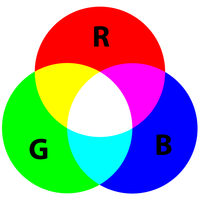
RGB was also known as Red, Green, and Blue. RGB color model is used as the basic color code in computer and television display. For your information, most of the computer display is made up of a million tri-color pixels. The combination of these 3 basic colors produces another form of color such as magenta, indigo, yellow and even white. The level of each basic color is represented from 0 to 255. How are we going to determine the color code? The simplest way is to open your MS paint.
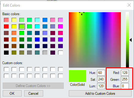
Open up your MS paint and select ‘edit color’ in the top right corner. After that, select the desired color and record down the code. For example, I recorded my favourite light green color. The code is R:128, G:255, B:0.
2) RGB LED hands-on
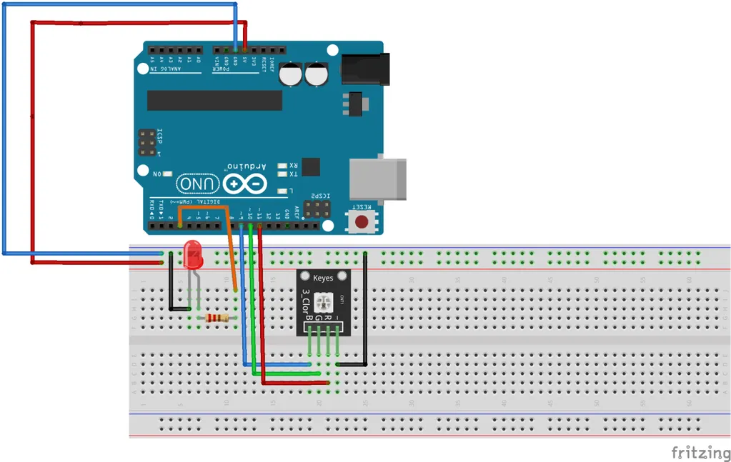
For this hand-on, I’m going to use the SMD type RGB LED module. You also allow using the basic tri-color LED such as this. However, be sure to ready 3 resistors to avoid the LED getting burn. Please visit my previous LED tutorial to calculate the resistance according to the LED color.
#define Red 11
#define Green 10
#define Blue 9

void setup()
{
  pinMode(Red,OUTPUT);
  pinMode(Green,OUTPUT);
  pinMode(Blue,OUTPUT);

  RGB(255,255,255);  //calling the RGB function
}

void loop()
{
}

void RGB(int red, int green, int blue)
{
  analogWrite(Red,red);
  analogWrite(Green,green);
  analogWrite(Blue,blue);
}
The only thing you need to do is to change the PWM value in the RGB function. Using the recorded value (R:128, G:255, B:0), Line 11 should be written as RGB(128,255,0). After everything is set up, compile and upload the following code to your Arduino. Finally observed the color.
Task 3: What have you learned from this tutorial
- You have learned the basic concept of PWM
- You know how to dim an LED and control the tri-color LED
- Basically you have learned the following code from this tutorial:
- analogWrite(Pin, PWM value) - Generate a PWM output with respect to the pin.
Conclusion
That’s all for the PWM hands-on tutorial write up. Hope you learn something new here. Until next time ;)
tags: arduino - beginner - tutorialThanks for reading. Follow my twitter for latest update
If you like this post, consider a small donation. Much appreciated. :)